1. Introduction
On behalf of Team Sanatron, we want to thank you for purchasing our products and letting us serve you. It is because of your support that we at Sanatron get to do what we are passionate about.
Our goal is to be your partner when it comes to vacuum technology. We are happy to help you design and build the world as we see it today. We also want to inspire you to rise above and to envision, develop, and build engineering systems for a better future tomorrow which seemed almost impossible today.
Click Here for the PDF Version of the Acrylic Vacuum Chamber USER MANUAL:USER MANUAL: [Document #:443302] - PDF
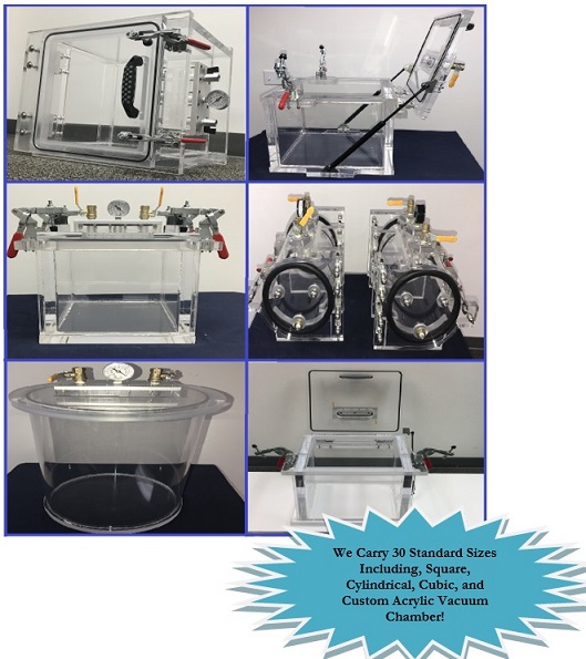
We carry a large selection of Acrylic Vacuum Chambers. We have standard sizes and options to customize chamber and even build turkey systems.
See our complete Acrylic Vacuum Chambers Catalog
Every chamber is specified, designed, built, and quality inspected by us specifically for you. In order to get the most out of your chamber, please take the time to fully read and understand this document.
Following this Installation, Operations, and Maintenance Manual will:
1. Ensures an effective and efficient operation.
2. Prolong the life and quality of this equipment.
3. Maintain a safe and secure work environment.
LEGAL NOTICE: Sanatron makes no warranties applying to information contained in this document or its suitability for any implied or inferred purpose. Sanatron shall not be held liable for any errors this manual contains or for any damages that result from its use. By using this chamber or manual, the user/operator agrees to operate this chamber voluntarily, at own discretion, and at their own risk.
Operator must comply with safety instructions, observe workplace safety rules, and follow regulations issued by corresponding government agencies.
WARNING: Misuse of this equipment may result in equipment damage or personal injury.
DO NOT make unapproved modifications to this chamber
2. Taking Care of your Acrylic Vacuum Chamber
WARNING: HEAVY!
Consider that the smallest and lightest Sanatron Acrylic Vacuum Chamber weights 35lbs or more. Please use the proper lifting and moving equipment while relocating your Chamber. Do not try to lift this Acrylic Chamber by yourself. Use the same procedures that you would use when handling heavy equipment. Consult your on-site Safety Engineer or Material Handler if you are not sure how to move heavy and fragile equipment.
WARNING: FRAGILE!
Acrylic is fragile and will crack or craze if dropped or mishandled. You must set your Acrylic Vacuum Chamber slowly down onto your work area. Additionally, do not hit it with sharp objects such as knifes, hammers, or screwdrivers. Do not collide this system with other objects. You must handle the acrylic carefully in order to maintain it.
ATTENTION! DO NOT use, apply, or expose SOLVENTS to Acrylic Chambers
Solvents have the ability to attack the surface of acrylics and dissolve the polymer chains which are the building blocks or acrylic. Not only will solvents dissolve acrylic and acrylic epoxy glue, solvents will also diffuse into the acrylic and acrylic glue and weaken it.
This includes, but is not limited to: isopropyl alcohol, acetone, paint thinners, and other solvents. Please do not use this chamber for Wood Impregnation as some Wood Resins outgas and the vapor from the wood resin will attack the acrylic and the acrylic epoxy glue and destabilize the acrylic vacuum chamber.
DO NOT use this chamber to dry parts that have been cleaned with including, but not limited to: isopropyl alcohol, acetone, paint thinners, and other solvents. The solvent drying vapors will attack the acrylic and the acrylic epoxy glue and weaken the acrylic vacuum chamber.
3. How to Clean the Acrylic Vessel
DO NOT USE SOLVENTS such as Alcohol, Acetone, or Chemical Thinners these will Damage and Craze your Acrylic and make it opaque making it difficult for you to see bubbles.
Approved Cleaning Methods are:
1. Water and Hand Soap
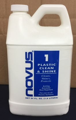
2. NOVUS, #1 Acrylic Cleaner
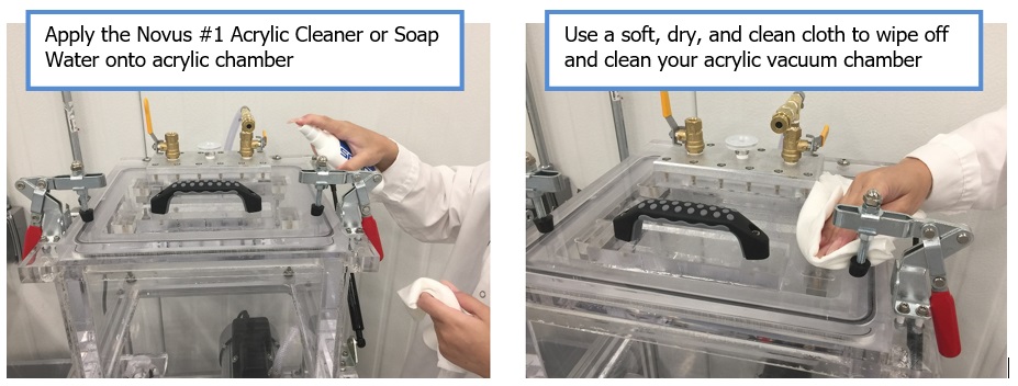
Use a lint free cloth by soaking or submersing it into water or soap water. Squeeze the water out of the cloth so that you end up with a damp cloth (containing water or soap water or #1 Acrylic Cleaner).
With the damp cloth, sweep across the acrylic surface until the dirt or dust have been picked up. Be careful not to scratch the acrylic.
Once you have swept your acrylic surface, use a dry cloth or paper towel to soak up the moisture from the acrylic surface. Finally, you can wipe off the wet surface with a dry cloth.
Finally, be sure NOT to use any soap which may contain alcohol or solvents.
4. Vacuum Chamber Specifications
A. Vacuum Rating
- All Acrylic Vacuum Chambers are rated to 0.075 Torr of absolute Pressure with the appropriate vacuum pump. This chamber will pull to 75 micron, -29.92 inHg, -14.69 psi, -101kPa.
- The highest vacuum you can pull is dependent on two things:
1. Your altitude and the ambient pressure: You can only pull as much air as is present in the chamber. At higher altitudes, the vacuum you can pull is lower
2. Your Vacuum Pump: The vacuum level is also Dependent on the vacuum pump you have. Make sure that you have a powerful enough pump to handle this acrylic vacuum chamber.
- The leak rate of this acrylic vacuum chamber is no less than 5.25 Torr (0.25 inHg) within the first 24 hours. This chamber will not lose much pressure after 24 hours and will hold the vacuum level steady for several weeks.
- The internal dimensional tolerances of this chamber are +/- 0.125 inch.
- Unless otherwise noted or requested in the quote, the chamber materials and the lid materials are made from Clear Cast Acrylic.
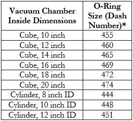
- The Standard Sealing Material is a Buna-N 1/4 inch (0.275” Actual) diameter O-Ring. Viton and other types of O-Rings are available upon Request.
B. Physical Properties
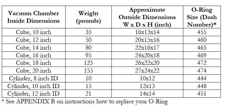
The chamber approximate weight and typical outside dimensions are show in table below:
C. Environmental Conditions for Operations
- This acrylic vacuum chamber is designed to be operated throughout all humidity levels.
- The temperature range for this chamber is -100 °C to 41°C (-150F to 104F)
5. Acrylic Vacuum Chamber Operations
A. Receiving and Unpacking your Chamber
Depending on the size, weight and complexity of your system, your vacuum chamber will arrive either in a box, crate, or pallet. Please be sure to unpack your item as soon as you can so that any damages incurred during freight can be handled quickly.
During your unpacking process be sure to inspect your item for damages. If you find your item to be damaged, please contact us and depending on the shipping terms, we will either help you resolve your case or refer you to the freight company.
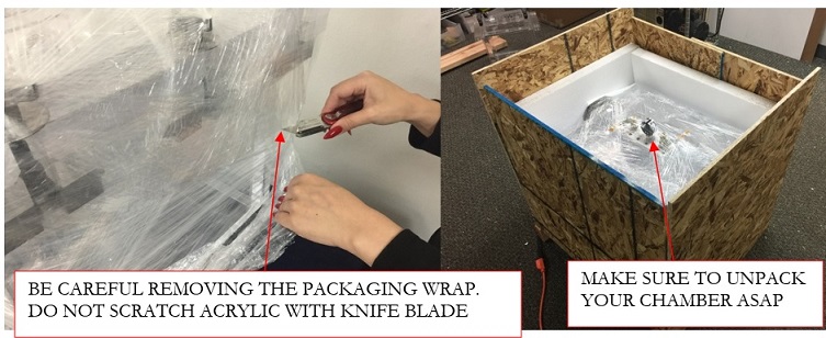
Note that your chamber will be wrapped into packaging wrap, be extra careful removing it and if you are using a knife to cut the wrap, be sure not to cut or scratch the vacuum chamber. KEEP THE KNIFE AWAY FROM ACRYLIC. DO NOT SCRATCH ACRYLIC CHAMBER.
Finally, be sure to handle your chamber with care as it is heavy.
As you unpack your vacuum chamber, you may notice Styrofoam pieces, saw dust, and heavy glue smell. The Styrofoam and sawdust are easy to clean. The glue smell may be present because your chamber is built in house and made to order and is still fresh. This smell will slowly decrease and become unnoticeable after a week or two.
B. Connecting your Vacuum Chamber to the Vacuum Pump
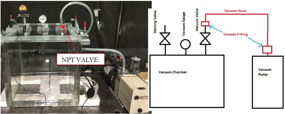
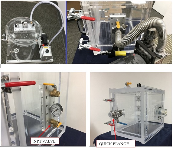
This acrylic vacuum chamber is fully setup and ready to go; all you need to do is to connect the acrylic vacuum chamber to the vacuum pump. Please see the sketch below to understand how the vacuum chamber connects to the vacuum pump.
There are two most common ways to connect the vacuum pump to the vacuum chamber:
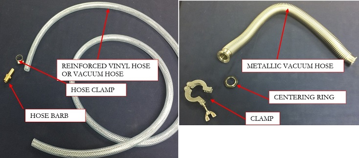
Barb Fitting: A barb Fitting is required to connect the vacuum chamber and vacuum pump. Since our standard vacuum valve is a 1/4 inch NPT, we suggest that you use a Barb that is 1/4 inch Male NPT by 3/8 Hose Diameter ID. You will also need a barb hose clamp. Repeat the same process for the vacuum pump.
NW Quick Flange: This is also an option that you have which is a bit better as it will decrease your pump-down times due to larger diameter hose. As an option we offer NW25 and NW40 Valve that can be connected to your chamber via a Metal Bellows Hose either NW25 or NW40. You will also need a Centering Ring and a Clamp.
Once you have connected your vacuum chamber with vacuum pump properly, it should look like the image below. Please see the images below as a reference to confirm that you have connected your vacuum chamber to vacuum pump:
C. Explanation of Vacuum Chamber Components
Your Vacuum Chamber comes with a Venting Valve, a Vacuum Gauge, and a Vacuum Valve.
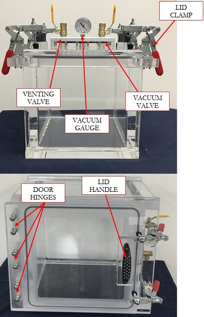
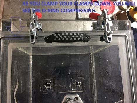
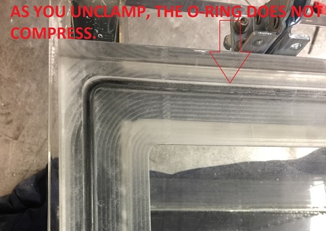
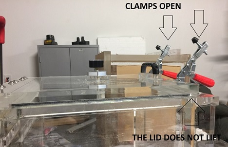
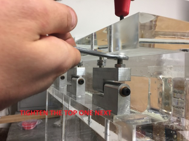
Lid Clamp is a toggle style clamp that is used to press the Lid and compress the O-Ring against the sealing surface. Most of the time, this clamp is use to initiate the vacuum at first. Once you have reached a -1psi vacuum, the vacuum force will create sufficient force to hold the O-Ring Sufficiently Compressed against the sealing surface.
The Top Load, Removable Lid Model has 4 clamps, the Hinged Side Door, Front Loading Model has 2, and the Spring Supported Lid has also 2 Clamps.
The Lid Handle is used to properly hold and move the vacuum chamber lid. Grab the lid Handles firmly to lift the lid from the top of the vacuum chamber. Conversely, grip the handle to open the front load and spring supported chamber.
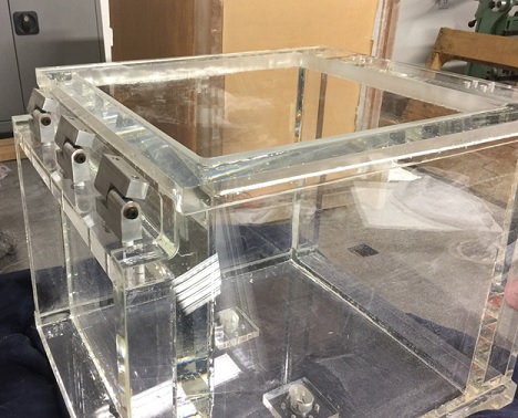
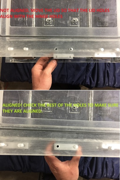
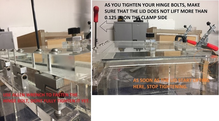
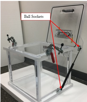
Door Hinges are present to hold the door in place and to enable you to swing the door open. Your vacuum chamber hinges will not need adjustment during the lifetime of the vacuum chamber. However, the good news is that our door hinges are the only ones on the market that are adjustable. Please see Appendix A for instructions on how to adjust the Door Hinges.
The Venting Valve is not connected to anything, it is simply there to vent your chamber once you are ready to release your vacuum. You may connect a muffler or a filter onto it so that you can prevent impurities rushing into your chamber as you are releasing your vacuum. In some instances, your venting valve can be used to control the vacuum levels inside your chamber. The way to do this is to not fully open the venting valve and watch the vacuum gauge reach your desired vacuum level. Once your desired vacuum level has been reached, watch the dial, if it moves toward higher vacuum, open your venting valve a bit more. If on the other hand, you are unable to reach your desired vacuum level, close the vacuum valve a bit more. You will have to play with it a little bit but once you have dialed in your vacuum valve position, you will not need to adjust your vacuum anymore.
A better way to do this vacuum control is to get a vacuum controller or a vacuum control valve installed on your system.
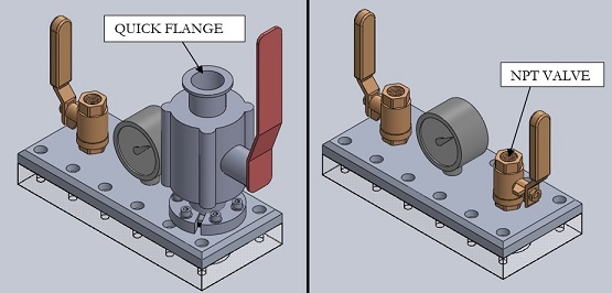
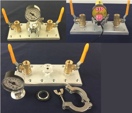
The Vacuum Gauge shows the vacuum level inside of your chamber. Your Dial Vacuum gauge comes with a 2% to 3% accuracy and is not calibrated. If you need your vacuum gauge calibrated or if you need your vacuum gauge to be quick release as shown in image below, please contact us and we will add this to your system as an option.
If you require a higher resolution vacuum display; we recommend that you install a Instrutech Stinger Gauge. This vacuum gauge is electrically powered and will display a vacuum output in Torr with 3 significant figures of accuracy. Once your vacuum level goes below 1 Torr, the vacuum display will switch to micro Torr (micron) output. This is a recommended option if you require a more accurate vacuum measurement.
Vacuum Gauge OptionsShown are two options.
First is the quick release option that will allow for easy and periodic vacuum gauge calibration.
The Second Option is the Instrutech Vacuum Gauge option which allows you to display your vacuum inside the acrylic vacuum chamber in Torr and with an accuracy of 3 significant figures.
The Vacuum Valve, which is connected to the Vacuum Pump is used to let the air be evacuated from the chamber.
D. Creating Vacuum inside your Vacuum Chamber
To create a Vacuum, simply:
1. Close the lid
2. Close clamps so that slight pressure is applied to the Lid and O-Ring.
3. Close the Venting Valve (the valve not connected to anything)
4. Turn ON the Vacuum Pump.
5. Open the Vacuum Valve (the valve that is connects the Vacuum Pump to your Vacuum Chamber)
6. Watch the vacuum gauge display and notice your vacuum increasing. Once you have reached your desired vacuum level, close the vacuum valve and hold your vacuum as long as you need to. Our vacuum chambers are designed to hold vacuum for an extended period of time.
E. Releasing Vacuum and Venting your Vacuum Chamber
Once you are done with operating your vacuum chamber, all you have to do is:
1. Open the Venting Valve and let the vacuum release (you will hear air rushing into your chamber).
2. Turn OFF the Vacuum Pump
3. Close the Vacuum Valve (the valve that is connects the Vacuum Pump to your Vacuum Chamber)
4. Keep the Venting Valve Open and Open or Remove the Lid.
Congratulations, you have successfully operated your acrylic vacuum chamber!
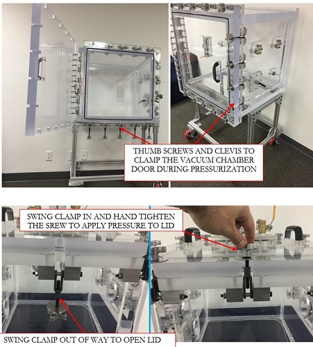
F. Pressurizing your Chamber
Your acrylic vacuum chamber can be pressurized, if you have purchased the OVERPRESSURE OPTION. The pressurization process is simple, simply connect your valve to compressed air source, but instead of vacuum, use compressed air instead.
The slight over-pressurization is usually 5psig, 10psig, or 15psig. This overpressure option enables for a broader and deeper application. Each over pressurization option comes with a vacuum rated pressure relief valve that will pop open at about 15% over the rated pressure in order to vent any additional chamber pressure and keep the system safe.
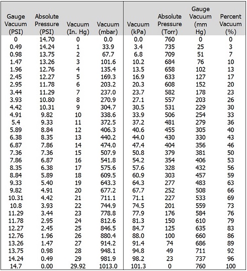
6. Conversion Tables
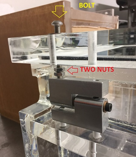
A. Pressure and Vacuum Conversion Table
B. Altitude vs. Pressure Conversion Table