Most medical device pouches and blister cards seal a breathable, porous lid over a rigid thermoformed tray, and that breathable lid is exactly what makes them hard to leak test well. CO2 tracer gas leak testing is the non-destructive method written for that structure. Here is how the method works, what size defects it finds, how it is calibrated, and where it fits beside bubble testing and helium tracer gas testing. For choosing among methods in general, see our overview of leak testing methods and techniques.
Table of Contents
What Is CO2 Tracer Gas Leak Testing?
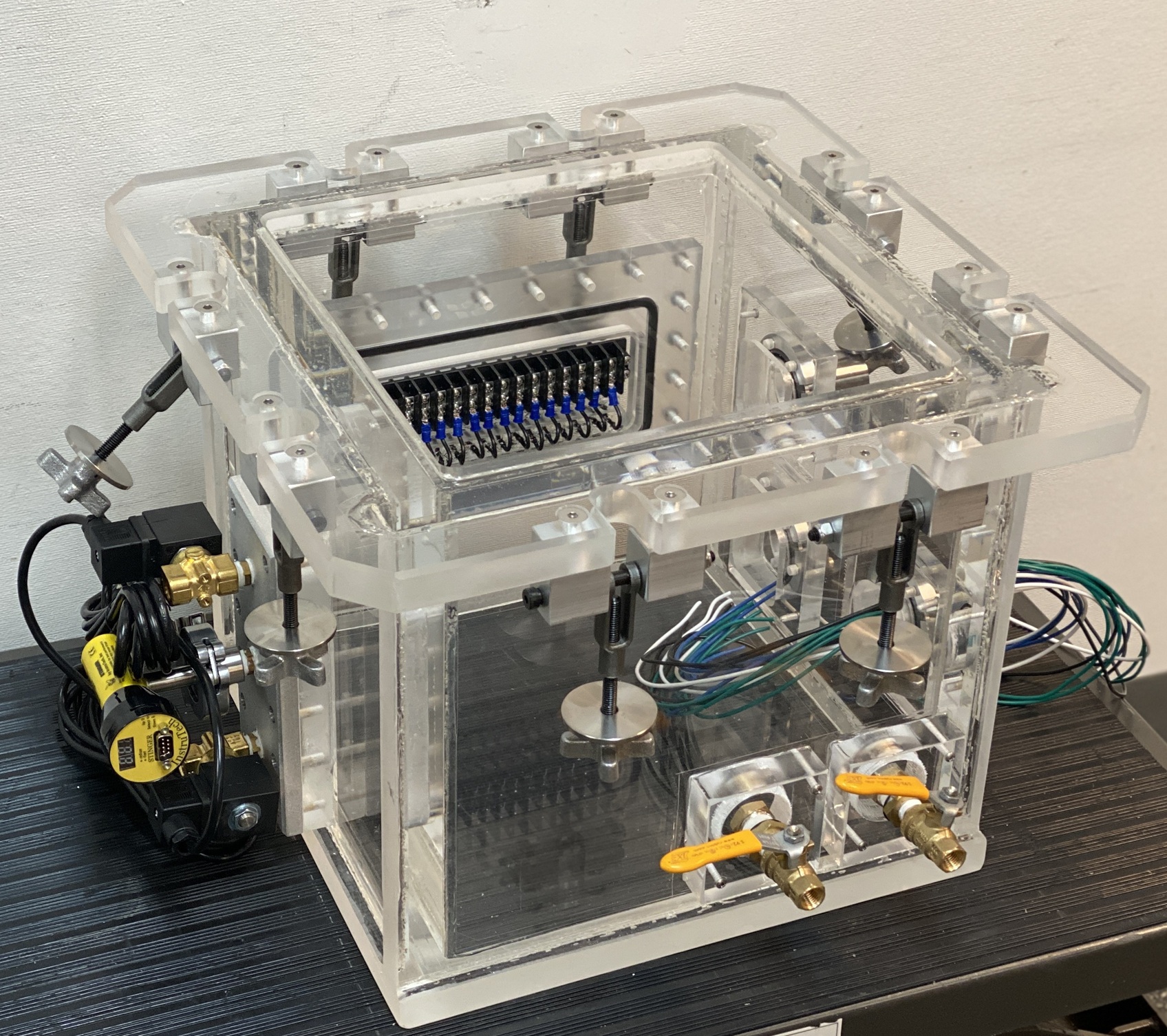
Two ASTM methods define the practice. ASTM F2227 covers bare, unsealed, empty medical packaging trays: it finds pinholes as small as 50 micrometers (0.002 inch) and equivalently sized cracks in the tray wall. ASTM F2228 extends the same physics to the finished assembly, detecting channel leaks in the seal between lid and flange as small as 100 micrometers (0.004 inch) along with those pinholes and cracks. Both are qualitative: the instrument returns an accept or reject signal, not a quantitative leak rate in the sense described in our article on understanding leaks and leak rates. And one boundary matters more than any other: neither method challenges the porous, breathable lid itself. The tracer reaches the package interior by passing through that lid under pressure, so the lid behaves as a diffuser, not as a part under test, and defects living inside the porous web are not found this way.
How Does the CO2 Tracer Gas Test Actually Work?
The apparatus has three essential parts: a test fixture whose sealing membrane closes off the top of the tray or lidded package, control packages with calibrated leaks, and an instrument built around an infrared CO2 sensor. A cylinder of commercial or bone-dry grade CO2, regulated to at least 30 psi, feeds the test gas. After warm-up, a typical cycle runs like this:
- 1. The package is centered in the fixture, lidding side up, and the cover closes so the CO2 port meets the package.
- 2. CO2 is flushed through the porous lid at a flow rate set to exchange the package's internal volume at least twice per cycle, driving the internal trace gas concentration toward 90 to 100 percent.
- 3. The internal CO2 sits at a gentle positive pressure, roughly 0.25 to 0.75 kilopascals, or about 1 to 3 inches of water column, while room air is simultaneously drawn past the sensor at a near-ambient vacuum of about 0.1 inch of water column.
- 4. Near the end of the flush-and-soak phase a valve closes that room-air flow so the capture volume over the lid returns to ambient pressure and escaping CO2 accumulates instead of being swept away.
- 5. At the end of the test the valve reopens and a pump pulls the capture-volume air through the infrared sensing chamber; if the CO2 there is meaningfully above room air, the instrument sounds its audible or visual alarm and the package is rejected.
Response is a non-linear function of hole size, and sensitivity depends on the tracer concentration achieved inside the package, which is why the flush rate is specified in tray volume exchanges per cycle rather than pressure alone.
Calibration, Basal Flow, and False Positives
The standard calls the expected bleed of tracer across the seal region basal flow: trace gas moving laterally through the porous lid and between the lid and the gasket made by the seal. Basal flow is noise, not a defect, and the setup exists to separate it from real leaks. That is why the methods mandate control packages: real packages built with calibrated capillary channel leaks and calibrated pinholes, used to verify the fixture and set the reject point for each package geometry. Calibration is expected at least daily, preferably at the start of every shift, and a fixture so large that the instrument cannot detect its calibrated control leak is a fixture too large, full stop.
False rejects are the practical failure mode. In the 2002 round robin behind the standards, all 216 tests on genuine calibrated leaks found the leak, but four of 108 tests on plugged pinholes (no leak) were false rejects, traced to dust on the sealing membrane. Clean the membrane with a lint-free cloth and recommended solvent, inspect it frequently, and qualify any membrane against your lid by watching for sticky residue, lifted fibers, texture changes, or lifted print on release. Treat the spent gas responsibly too: CO2 is inert and non-toxic, but it suffocates by displacing oxygen, so vent it away from the operator and keep the room ventilated.
When Should You Choose CO2 Tracer Testing Over Helium or Decay Methods?
Choose CO2 tracer testing when your package is a porous-lidded medical device pouch or a bare tray and you need a pass/fail decision an operator on any shift can run without interpretation. It is non-destructive, so high-value finished assemblies survive the test, and it suits statistical sampling and package development work, even though a single instrument is typically too slow for a full production line. Where you need quantitative sensitivity or must fine-test the porous web itself, choose helium: our helium tracer gas article covers that family in vacuum and sniffer modes. When a CO2 failure needs root-cause confirmation, a bubble check per ASTM F2096 internal pressurization is the usual follow-on.
Let Sanatron Spec Your Package Integrity Test System
A CO2 tracer station is only as good as the fixture under the membrane, and that fixture is a vacuum-tight chamber problem as much as a sensor problem. Sanatron builds custom test chambers and complete leak testing systems, including helium tracer gas systems for the confirmation work this method cannot do. Tell us your tray geometry, your lid, and the calibrated leak the fixture must prove, and we will size the chamber, the pumping path, and the instrumentation around them. Start the conversation at Contact Us before your next design freeze.
Frequently Asked Questions
What is CO2 tracer gas leak testing?
It is a non-destructive package integrity test defined by ASTM F2227 and F2228. Carbon dioxide is flushed into the package under a small positive pressure through its porous lid; if the tray or seal has a leak, CO2 escapes into a capture volume, is drawn past an infrared CO2 sensor, and the instrument signals a pass or fail without operator interpretation.
What size leaks can CO2 tracer gas leak testing detect?
The methods are written to detect channel leaks in the seal as small as 100 micrometers (0.004 inch) in diameter and pinholes, or equivalently sized cracks, as small as 50 micrometers (0.002 inch), provided the trace gas concentration inside the package, the package design, and manufacturing tolerances allow it.
Can CO2 tracer testing find leaks through breathable packaging?
No. The method explicitly does not challenge the porous, breathable lidding material itself. It finds pinholes and cracks in the rigid tray and channel leaks between the lid and the tray flange; defects within the porous portion of the package will not be detected by this method.
Is CO2 tracer gas leak testing destructive?
No. It is a non-destructive inspection, which matters when the unit under test is a high-value finished package. The only consumables are the CO2 trace gas itself and the temporary sealing membrane, which must bond gas-tightly to the porous lid during the test and release cleanly afterward.
How often should a CO2 leak tester be calibrated?
Calibration is performed with control packages that carry calibrated capillary channel leaks or calibrated pinholes, and the guidance is at least once a day, preferably at the start of every shift. Calibration verifies the whole fixture and instrument chain and sets the sensitivity and baseline for each package geometry.
Related Articles:
■ Helium Leak Testing: The Tracer Gas Method Explained
■ Top 5 Leak Testing Methods and Techniques Everyone Must Know
■ Understanding Leaks and Leak Rates for Best Quality Leak Testing
Some of our Popular Items
We are an Engineering Excellence Company. There is a tremendous amount of valuable resources and information regarding vacuum systems and vacuum technology; check them out by clicking on the links below.