When a Leak Test Fails: Is It the Part or the Test?
Every leak test on the planet leaks a little. The question is never whether your specimen will hold a perfect seal, it is whether the leak is inside the tolerance your process demands. When a pressure decay or vacuum decay test fails, the failure usually comes from one of two places: a real breach in the part, or an error in the way the test was set up and run. The curve itself tells you which one you have, if you know how to read it. If you have not yet studied the four phases of the decay curve, read Anatomy of the Pressure Decay, Vacuum Decay, and Force Decay Curve first. This article picks up where that one leaves off: turning curve anomalies into root causes.
Fill Phase Failures: Gross Leaks and Bad Set Up
The fill phase is where gross leaks expose themselves. If the signal rises more slowly than your known-good baseline, the suspects are a major gross leak in the test specimen, a part that was loaded improperly, or a connection that was never sealed in the first place. If the slope is steeper than usual, you are almost certainly looking at a test error, not a part defect: the wrong recipe is loaded, the wrong part is in the chamber, or the test did not run as programmed.
A quick diagnostic checklist before you reject any part:
- Is the correct recipe and set point loaded for this specific part number?
- Is the specimen seated correctly against the seal, with no debris or product occluding the seal path?
- Are fittings, vacuum valves, and connection hardware tight and leak-free?
- Is the vacuum pump actually reaching the evacuation level the recipe expects?
Symptom to Root Cause: A Quick Reference Table
Once the valve closes, the settle phase should bring the specimen to equilibrium. Curve behavior in this region is where most false failures are born, because trapped air and material behavior can look exactly like a leak. Use the table below to map what you see to what it most likely means.
| Symptom on the Curve | Most Likely Root Cause |
|---|---|
| Signal keeps rising after the valve closes | Filling/evacuation valve did not actually close; wrong recipe; test did not run properly |
| Signal drifts down faster than baseline | Real micro leak, or a virtual leak (trapped air slowly releasing from the assembly) being mistaken for one |
| Signal stays perfectly flat when it should drift slightly | Test sensor is not recording; verify the instrument before trusting a PASS |
| Vent curve is horizontal | Vent valve did not open; specimen never returned to ambient |
| Vent recovery is slower or weaker than usual | The test altered the specimen; you may be running a destructive test without knowing it |
One caution from experience: not every drifting curve means a bad seal. Air trapped inside a hollow part or between a bolt and a chamber wall escapes slowly as pressure changes, creating the illusion of a leak. These virtual leaks are not physical breaches, and they are best eliminated at the design and assembly stage by venting trapped volumes before they ever reach your test stand. Temperature is the other classic imposter: a part that is warmer than the chamber environment will move gas, and gas movement reads as decay.
Reducing False Failures: Best Practices
- Establish and store a known-good baseline curve for every part number, so "abnormal" has a reference point.
- Give every part in a fixture the same seal path and fixturing method, so operator variation does not become curve variation.
- Let the specimen reach thermal equilibrium before the test window opens, and keep settle times long enough to pass the turbulent early decay.
- Rule out virtual leaks during design by venting blind volumes, then re-test suspect parts before scrapping them.
- When decay testing cannot resolve a marginal part, escalate to a definitive method such as helium leak testing, which distinguishes real leaks from trapped air by sniffing the tracer gas.
Conclusion: Let the Curve Do the Debugging
Even if your decay test fails, it is still valuable information. Fill-phase behavior separates gross leaks from set-up mistakes, settle and test phase shape separates real micro leaks from virtual leaks and temperature drift, and vent behavior tells you whether the test itself damaged the specimen. The faster your team can route a failure from symptom to root cause, the fewer good parts get scrapped and the faster real process problems get fixed.
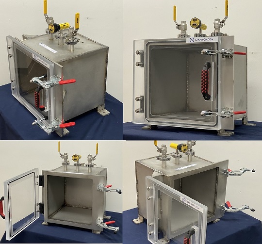
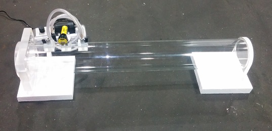
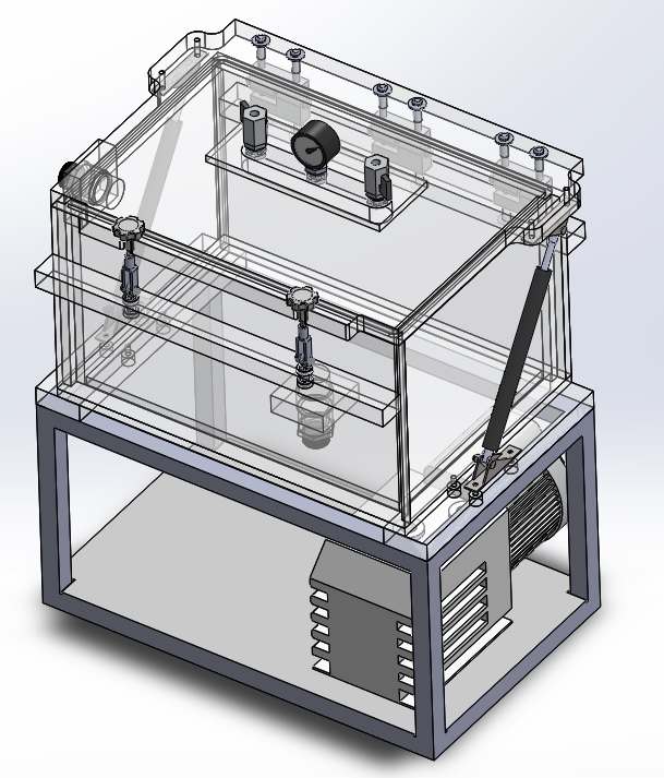
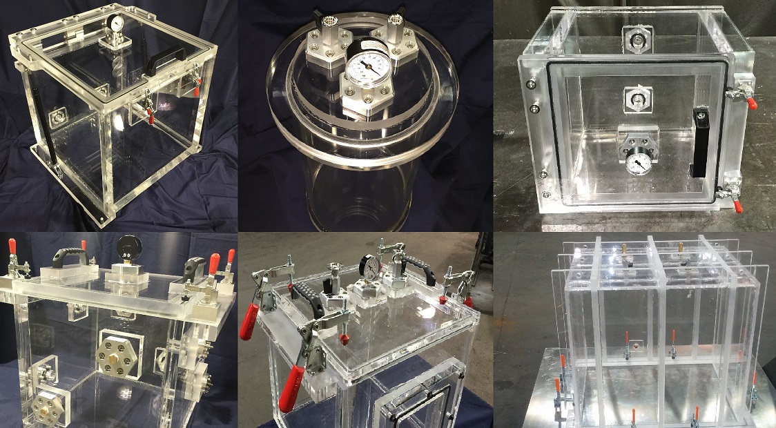
Sanatron builds complete decay leak test cells and the components they run on: clear and stainless steel vacuum chambers, vacuum pumps, valves, fittings, and automated test systems with recipe-based controllers that capture the entire curve for every specimen. If you are fighting false failures, marginal pass/fail decisions, or an operator-dependent test process, our engineers will design a system that makes your curve repeatable and your root cause easy to read. Contact Us today to talk about your leak testing application.